CHANGES ARE INDICATED UNLESS OTHERWISE NOTED ALL VENT CONNS. Spool number are sub divisions of Line number given during fabrication to facilitate transportation of pipelines, the spools are connected on-site to complete the line. FIELD WELD JOINTS WHERE SPECIFICALLY ARE INDICATED (FW), VENT DRAIN CONNECTIONS ARE INDICATED (V) SPEC.

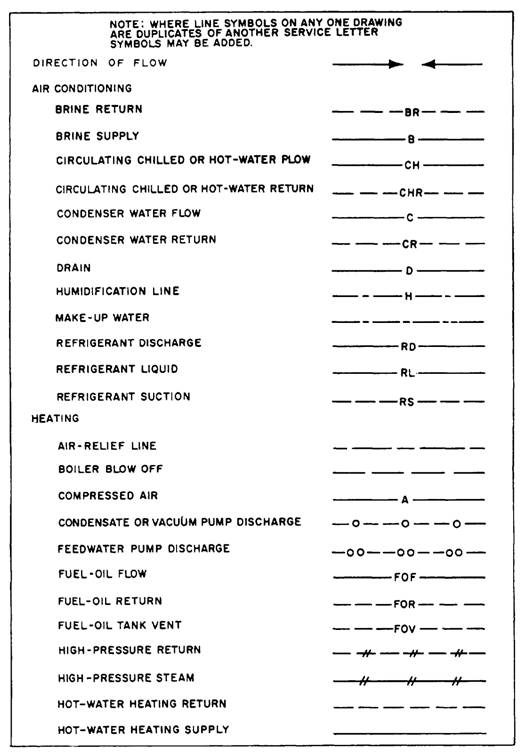
Line number is given to each individual pipe line and the number is applicable for its whole length, until it joints to another pipeline or a equipment. Symbols of Pipe Line Isometric Drawingsĭirection symbol is given on top of Pipe Line Isometric drawing to determine the directions of pipelines.This Blog gives a detail study of P&ID and Pipe Isometrics, with details of Įxample of a P & ID is given below in figure-Bįigure B : Example of P & ID ( Piping and Instrumentation Drawing ) P & ID : is called as Piping and Instrumentation Drawing, is a pictorial representation of Pipeline in a single line diagram along with processing Equipments/ Instruments and storage tanks. Isometric drawings of drain, waste and vent (d.w.v.) must include the size, location and type of pipe.

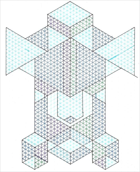
Pipe Isometrics : Are drawings which shows details of Process pipe lines in a single line presentation, with details of pipes, pipe connections ( valves, flanges, nipples, reducers, end cap, elbow, etc), along with the dimensions and direction of pipe line.Įxample of a Pipe Line Isometric Drawings is given below in figure-Aįigure A: Example of Pipe Isometric Drawing Piping and Instrument Diagram Standard Symbols Detailed Documentation provides a standard set of shapes & symbols for documenting P&ID and PFD, including standard shapes of instrument, valves, pump, heating exchanges, mixers, crushers, vessels, compressors, filters, motors and connecting shapes. An isometric drawing is a type of pictorial drawing in which three sides of an object can be seen in one view.


 0 kommentar(er)
